Introduction
This project aims to create a custom power profiler from sub-nA measurement up to 500 mA. It is based on the analog circuitry designed by Dave from EEVBlog in his uCurrentMeter [Link].
Dave’s project requires a multimeter to measure the voltage drop in a shunt resistor, which depends on the range that the device is measuring. The device only works on one range at a time, requiring the user to switch between channels (nanoamperes, microamperes and milliamperes) by a physical switch. Therefore, the uCurrent is ideal only if the current being measured does not require dynamic range switching
For my projects, I need to log the current consumption of devices as they transition between normal operation and low-power modes. Usually my projects are based around STM32 or ESP32 microcontrollers, which requires from hundreds of milliamps in normal mode (e.g.:300mA the ESP32 when using WiFi) down to dozens of microamps for the STM32 low power mode.
The microPowerMeter (Name TBD)
The microPowerMeter is a project aim to add the required extra features to the the circuit in the uCurrent, that is:
- Read current from nA range to mA.
- Automatic channel switch.
- Logging capabilities through USB for later data analysis.
- (Optional) Screen for standalone use.
There are similar other projects:
- Power Profiler Kit (100€): 0.2µA resolution, 200nA to 1A, 100Ksps, 0.8-5 Vcc, includes Logic analyzer.
- Otii Arc Pro (1000€): Accuracy 50nA, 50nA to 2.5A, 4ksps in low current range.
- JouleScope (1000€): 0.5nA resolution, 15V, 3A, 2Msps
There are alternatives to my microPowerMeter, however they lack the range (Power Profiler) or I lack the money (Otii Arc Pro or JouleScope). So, my plan is to create a custom version at lower cost but with the required current range.
Version 1.0 (January 2026)
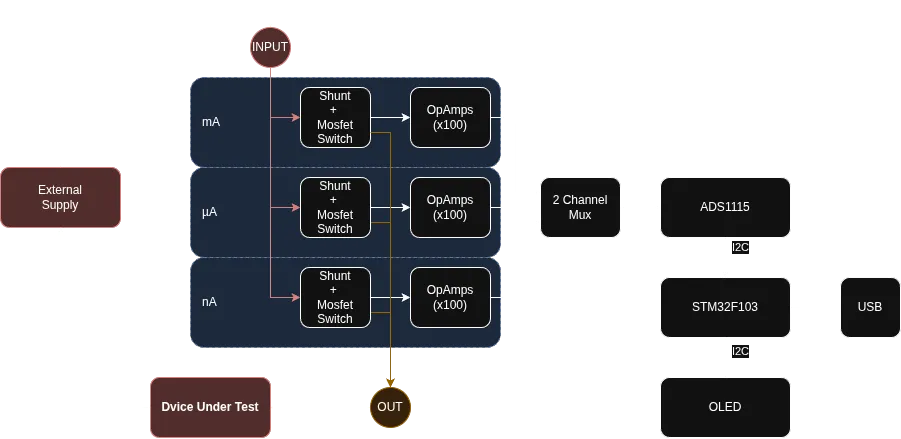
Design
In the first version of the uPM I just wanted to add a microprocessor to get the data and send it to the PC using a USB. The aim in this step is to do an affordable, and easily available components.
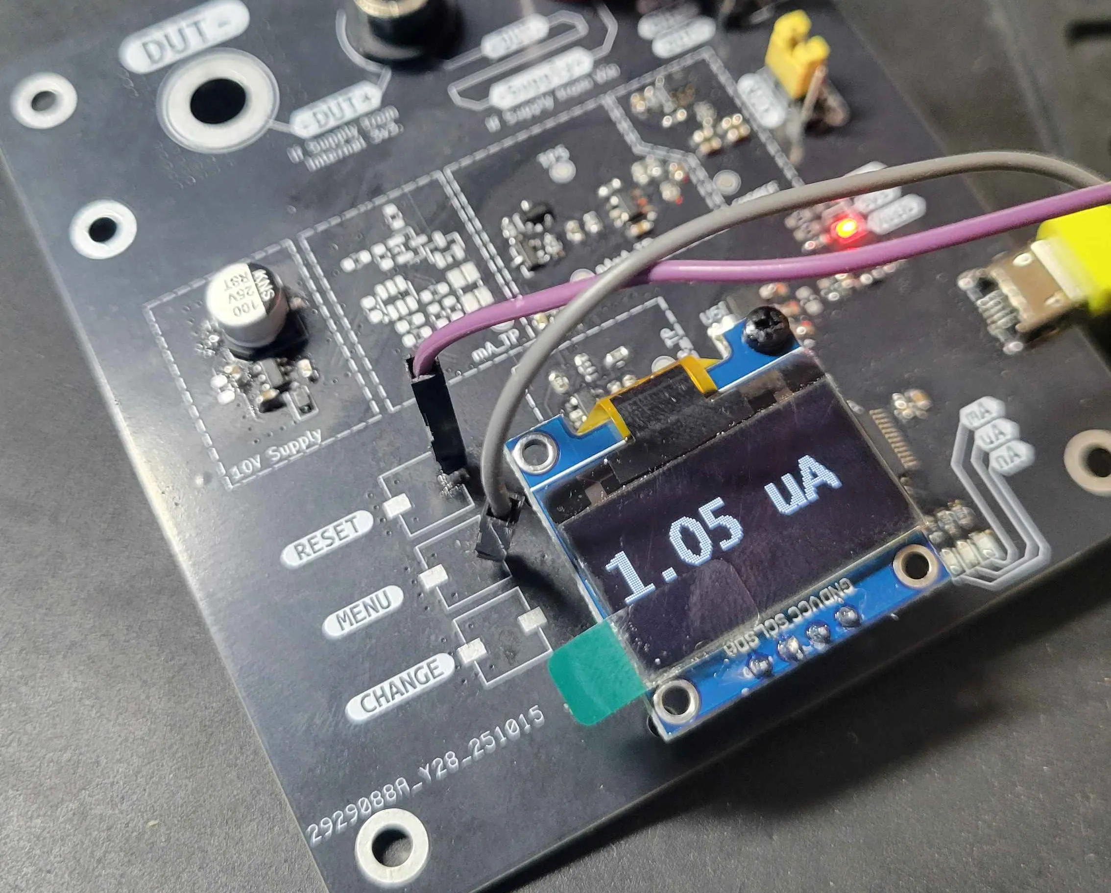
From my backgroun in the Maker world, I am used to work with the STM32F103 from which I have some bluepills (Aliexpress) and some ADS1115 (Aliexpress) modules laying around. Also for this version, I also added a typical 0.96 inches OLED screen (Aliexpress) to show the measurements.
First test and problems.
The STM32F103 main tasks was to read the ADC from the ADS1115, and send it to the Host PC using USB, if you want to know how add Tiny USB support to STM32 microcontrollers you can check this blog post.
Pretty simple design, which actually seems to work in the µA range. However, during extensive testing, the device several issues began to emerge. In the image below, the device is working with 1 µA, but analyzing the data from the PC shows the real thruth. The signal captured by the device contains a high 50Hz signal coupled into the actual signal.
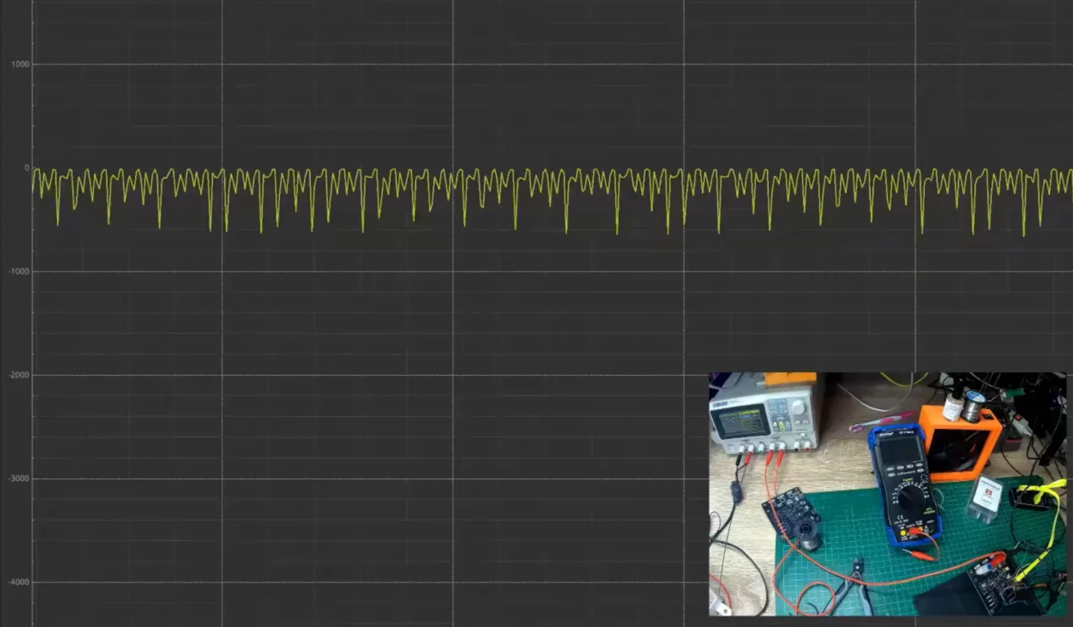
Mains voltage coupling
I had heard about this issue, but never experience myself. When working in regular projects, AC coupling usually is not a problem. The hundreds of microamperes flowing though the circuit do not affect the measurements or the device’s functionalities. However, in this project, the voltage drop in the shunt resistor is in the range of µA in a 10 , even the lowest current can create a measurable noise.
The mains coupling is a problem that appears when the mains frequency (in Spain 50 Hz) is capacitive coupled to the circuit. The circuit, the probes, the cabling, everything couples with the main voltage, thus generating a small AC current flow through the circuit. This small current generates the noise in the measuring shunt.

#