DC motor to microcontroller
When getting started in the maker world, one of the most fascinating milestones, right after blinking your first led, is **driving a motor. ** There are several types of motors: steppers, brushed, brushless, and more. Among them, the brushed DC motor is the easiest one to work with. Also this kind of motors are found everywhere from a normal printer to kids’ toy, and are so affordable, so burning one won’t hurt your pocket too much!

In order to test a scanvenged motor, the approach its to connect a power supply, start at 5V, and gradually increase the voltage until the motor begins to spin. Don’t worry about polarity! these motors don’t have a fixed polarity; they just spin one direction or the other depending on how you connect the leads.
While connecting a motor to a constant DC voltage gets it moving, the real fun begins when there is a microcontroller (like Arduino/ESP32/STM32) controlling the speed of the motor. Today I want to show you different methods for controlling both the speed and direction of a DC motor using a microcontroller.
Note
For this project we will need a microcontroller, any modern one will do. For the simple control only one GPIO is required, to enable speed control, a PWM signal shall be generated.
The examples shown here will be based on Arduino, but porting this code to any other programing platform should be enough.
Simplest: Mosfet + PWM
Component list
- MOSFET: For 3.3V logic, I recommend the IRLZ44N
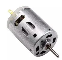
- DC Motor: Any small motor will work for example this one
On/Off control using MOSFET
The first idea that may come to your mind the first time you face this problem, is to connect the GPIO of the microcontroller directly to the motor. If the GPIO outputs 3.3V and
your motor runs on 3.3V, what’s the catch?
The issue here is that a motor requires anywhere from a few hundreds milliamp (mA) up to several amperes. Even the smallest motor’s current draw can easily fry your microcontroller.
Most GPIO pins are only designed to provide around 20-40mA, so trying to power a motor directly is a recipe for** ‘magic smoke’**!.
Tip
Always remember that microcontrollers are the “brains,” but they don’t have the “muscles” to move motors directly. For that, we need a driver.
In order to handle the motor current, we need an intermediate component: a MOSFET.
You can think of a MOSFET as a voltage-controlled switch (or more technically, a voltage-controlled current source).
When choosing a MOSFET, one of the most critical specifications to keep in mind is the , or threshold voltage.
This is the minimum voltage required at the gate to ‘turn on’ the MOSFET and allow current to flow from the Drain to the Source.
The MOSFET theory is beyond the scope of this post, but we can greatly simplify its working principle for this project. Think of the MOSFET as a high-speed switch: When the voltage at the Gate is equal to or greater than 3.3V, the MOSFET ‘closes’ and allows current to flow. Conversely, when the Gate voltage is close to GND, the MOSFET ‘opens,’ blocking any current from passing through. This allows us to control a high-current motor using only a tiny signal from our microcontroller. The circuit schematic can be seen bellow.
Warning
Even if the MOSFET is “on” at 3.3V, it might get a bit warm if the motor draws a lot of current. If you’re running a heavy load, don’t forget to check if you need a small heatsink!
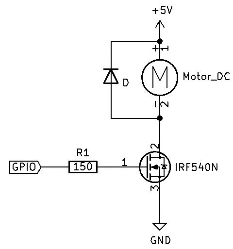
As you can see, the diagram includes a diode in parallel to the motor, this is called ‘flyback diode’. This diode prevent from current spikes that are created when the motor suddenly stop. Apart from that, the source code to control it is really simple.
// Motor GPIO#define GPIO_MOTOR 10
void setup(){ pinMode(GPIO_MOTOR, OUTPUT);}void loop(){ // Turn on the motor digitalWrite(GPIO_MOTOR, HIGH); delay(1000); // Turn off the motor digitalWrite(GPIO_MOTOR, LOW); delay(1000);}PWM Speed control
In the last example we just controlled the motor between on/off, but this is borint. We can make the most from the PWM signals.
We can use them to control the speed of the motor, not just the on/off state.
Arduino provides the analogWrite funtion on PWM capable signals, while for other libraries and microsontrollers, you should find how to use the PWM.
// Motor GPIO#define GPIO_MOTOR 10
void setup(){ pinMode(GPIO_MOTOR, OUTPUT);}
void loop(){ // Motor at 0% analogWrite(GPIO_MOTOR, 0); delay(1000); // Motor at 50% analogWrite(GPIO_MOTOR, 127); delay(1000); // Motor at 75% analogWrite(GPIO_MOTOR, 191); delay(1000); // Motor at 100% analogWrite(GPIO_MOTOR, 255); delay(1000);}Motor controller
L298N
Note
TODO: This section has to be added. However, the L298N driver is obsolete compared to most modern controllers like the TB6612FNG.
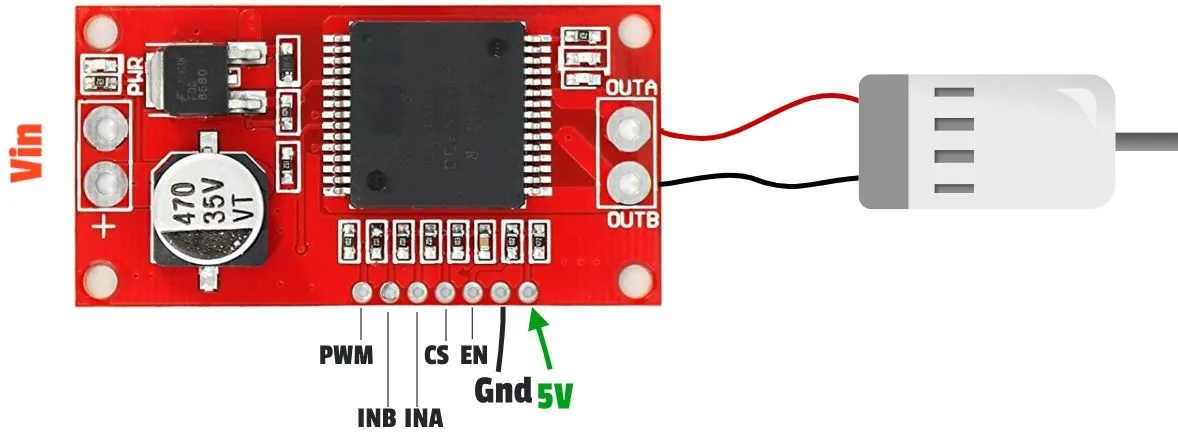
VNH2SP30
The VNH2SP30 is a DC motor driver, which includes an H-bridge, that is capable of handling up to 14A continious and peaks of 30A. The control interface for this driver is as usual.